A customer brought in a laptop that was having multiple issues. The laptop was from Dell (N5110) and fairly new with an Intel i3 processor and Windows 7 Home (64bit).
The first thing I noticed was that it was stuck in a Start Up Repair loop. This only happened after the computer was Shut Down, but not on a Restart.
Once the OS was stable and I was at the desktop I had an error come up.
"GfxUI.exe has stopped working."
This was a simple enough fix with an update of the Graphics Card driver from the Intel web site. I first had to find what type of Graphics Card was being used by going to Device Manager and expanding the Graphics selection and looking at the properties. Looking at the description of the Driver gave me a very basic idea of what kind of card I was using, but to my surprise Intel had that exact driver. (Intel HD Graphics)
While searching for the driver I noticed something odd. My Google searches were returning fine, but my links were being redirected to odd places and advertisements. I was able to download Google Chrome from a cached link and that helped in getting the Virus remover tools I needed to fix this problem.
After installing AVG and Malwarebytes and finding no viruses I had to do some digging and found that Kaspersky created a special Redirector Virus Remover for Rootkit.Win32.TDSS. I downloaded, installed and ran it and took care of that problem.
I then installed all Windows updates and shut down the computer to complete the installation. The Start Up Repair Loop was still in effect. After each Start Up Repair all Windows updates were shown to be needed again.
After much research I found a web post talking about a BIOS mismatch with released Microsoft Windows 7 updates. It was with great relief that I found this, because all other information lead to Format/Reinstall Windows. I never want to do this unless absolutely necessary and after I've cloned the disk.
After the machine went through the Repair and came to the desktop I downloaded the new BIOS from Dell that, which coincidentally, was released not long after the User began having problems with the laptop. Problems began on 7/16 and the user did an emergency back up of the drive. Dell released the BIOS update on 7/24. It was easy enough to install with a simple download, run, install, and reboot.
I was then able to do all Windows Updates, Shut Down the computer and bring it back up with no Windows Start Up Repair kicking in.
The user got the virus removed, new BIOS, new Anti Virus Software, Google Chrome, and all Windows Updates installed. I created a restore point in Windows and labeled it so anyone would know that this point is where all problems were fixed and should be used in case of emergency. I also asked the customer to do another back up and keep it in case of emergency.
This particular person had been my customer for years and knew the importance of back ups from other computer problems they have had. I recommend you do a full back up of the drive you are working on before you do any BIOS updates. BIOS updates are light years beyond what they used to be, but they are still known to crash some systems completely.
A virus infected back up is much better than complete data loss.
Sunday, July 31, 2011

Friday, October 16, 2009
Vonage Error Code 007 and a Fax Machine
If you use Vonage and have a Fax Machine or all in one machine you may have run across a [Code 007] error.
If you split your telephone jack with a Y Splitter and connect one port of the Y Splitter to your Vonage Device and the other to your Fax line you may get this error.
Error [Code 007] - Check to see if you plugged your phone into the wrong green phone port on your Vonage Device.
A way to fix this is to first check the phone cables that you are using.
You want a two wire telephone cable not a four wire telephone cable.
Plug the two wire telephone cable into one port of the Y Splitter and run that as your Fax line. Then run the other to the Line 1 of the Vonage Device. You can now add the telephone to the phone port of the Fax machine.
Below is a diagram of the set up:
 This should fix your [Code 007] error code unless you really are plugging into the wrong green phone port.
If you split your telephone jack with a Y Splitter and connect one port of the Y Splitter to your Vonage Device and the other to your Fax line you may get this error.
Error [Code 007] - Check to see if you plugged your phone into the wrong green phone port on your Vonage Device.
A way to fix this is to first check the phone cables that you are using.
You want a two wire telephone cable not a four wire telephone cable.
Plug the two wire telephone cable into one port of the Y Splitter and run that as your Fax line. Then run the other to the Line 1 of the Vonage Device. You can now add the telephone to the phone port of the Fax machine.
Below is a diagram of the set up:
 This should fix your [Code 007] error code unless you really are plugging into the wrong green phone port.
Thursday, June 4, 2009
Extended T1 from Cat 5 Keystone to Patch Panel
Here is a way to extend a T1 from a smart jack to a patch panel. I personally recommend dropping another data run for this, but if you don't have that option here is a set up you can use.
Material Needed:
4 patch cables or RJ45 Standard Straight-Through cables
2 Cat 5e Snap In Jack (Keystone)
1 Wall Mount Cat 5e Keystone Jack
Since you are going to use all the pairs in the cable you might need to disable the current T1 extension to make this work. I will use the 568B standard and Leviton R24-5G108-RV5 CAT5e Jack for this example.
First pair for the existing T1 will be (Blue - Blue/White) ~ (Orange - Orange/White). This pair will run to the same colors on the keystone. Punch this first pair down on the Blue/White - Blue - Orange/White - Orange on the patch panel.
The second T1 will be punched down on the keystone a bit differently. Start by punching down the Brown pair. With Brown going to the Orange and Brown/White going to Orange/White.
The Green pair will go Green/White to Green/White (Pin 3)and Green to Blue (Pin 4). Here is a diagram of the Keystones and the wire assignments below:
Keystone pin out:

Wire Assignments:

You can test your pair now by connecting a patch cable from the jack to the smart jack. If everything is connected properly you will see all green lights on the smart jack.
This now has to be terminated at the patch panel. Punch all 4 pair down the same way on different ports.
Here is a diagram of this pin out:
Patch Panel Termination:

Now that you have both T1's extended on one Cat 5e cable you can now use the patch cables.
Plug the cable into the wall mount jack and insert the other end into the smart jack RJ45 port. Back at the patch panel you will plug into your assigned port with one end and into the appropriate port at the router.
On the smart jack you should have all green lights and on the router you should see the carrier detect (CD) light as green.
JS
Material Needed:
4 patch cables or RJ45 Standard Straight-Through cables
2 Cat 5e Snap In Jack (Keystone)
1 Wall Mount Cat 5e Keystone Jack
Since you are going to use all the pairs in the cable you might need to disable the current T1 extension to make this work. I will use the 568B standard and Leviton R24-5G108-RV5 CAT5e Jack for this example.
First pair for the existing T1 will be (Blue - Blue/White) ~ (Orange - Orange/White). This pair will run to the same colors on the keystone. Punch this first pair down on the Blue/White - Blue - Orange/White - Orange on the patch panel.
The second T1 will be punched down on the keystone a bit differently. Start by punching down the Brown pair. With Brown going to the Orange and Brown/White going to Orange/White.
The Green pair will go Green/White to Green/White (Pin 3)and Green to Blue (Pin 4). Here is a diagram of the Keystones and the wire assignments below:
Keystone pin out:

Wire Assignments:

You can test your pair now by connecting a patch cable from the jack to the smart jack. If everything is connected properly you will see all green lights on the smart jack.
This now has to be terminated at the patch panel. Punch all 4 pair down the same way on different ports.
Here is a diagram of this pin out:
Patch Panel Termination:

Now that you have both T1's extended on one Cat 5e cable you can now use the patch cables.
Plug the cable into the wall mount jack and insert the other end into the smart jack RJ45 port. Back at the patch panel you will plug into your assigned port with one end and into the appropriate port at the router.
On the smart jack you should have all green lights and on the router you should see the carrier detect (CD) light as green.
JS
Friday, May 1, 2009
T1 from Westell NID through 66 Block
Telco companies are using outside NID's as T1 Smart Jacks more and more. This cuts down on the Telco installers time from installing inside wiring, but it leaves the end user to finish the job.
Below is a how to for extending the T1 from the NID to the Demark inside the building. I will use the Westell DuetPak as the NID example.
Here is a picture of the Westell NID:
 Here is a Spec Sheet for this NID.
As you can see the T1 boards are installed in the left side of the NID and routed through to the right side via an RJ45 jack.
The first thing you should do is grab a pencil and paper and mark down which pair will be the Rx and Tx to extend. What colors are going from the NID and what color the 25 pair will be spliced to. I also recommend killing the extended current by removing the RJ45 male end that is between the right and left side of the 4 posts you will be working with.
Before you start the run make sure to trace all your pair and mark them.
Using 1 and 2 (Black and Yellow) on the right side of the NID as Rx and 4,5 (Green and Red) as the Tx end.
Here is a drawn picture of the NID above with extended pair that will be spliced to the Telco 25 twisted pair and will run to the Demark 66 block inside the building.

This is with the 25 twisted pair spliced:

From here you will continue the run to the 66 Block at the demarcation point. This is what it will look like with the left side being the Telco side and the right side will run to your T1 Jack.
 The right side of this 66 block will run to your T1 Jack and in the end will look like this:
 In the end what is being accomplished is an extension of electricity from the origin (or close enough) to the end point. So just try to keep all the wire colors consistent so you can follow them start to finish. Mark your wires at the NID, 66 Block and label the jack when you are finished then hook it up to your router and you should be good to go.
JS
Below is a how to for extending the T1 from the NID to the Demark inside the building. I will use the Westell DuetPak as the NID example.
Here is a picture of the Westell NID:
 Here is a Spec Sheet for this NID.
As you can see the T1 boards are installed in the left side of the NID and routed through to the right side via an RJ45 jack.
The first thing you should do is grab a pencil and paper and mark down which pair will be the Rx and Tx to extend. What colors are going from the NID and what color the 25 pair will be spliced to. I also recommend killing the extended current by removing the RJ45 male end that is between the right and left side of the 4 posts you will be working with.
Before you start the run make sure to trace all your pair and mark them.
Using 1 and 2 (Black and Yellow) on the right side of the NID as Rx and 4,5 (Green and Red) as the Tx end.
Here is a drawn picture of the NID above with extended pair that will be spliced to the Telco 25 twisted pair and will run to the Demark 66 block inside the building.

This is with the 25 twisted pair spliced:

From here you will continue the run to the 66 Block at the demarcation point. This is what it will look like with the left side being the Telco side and the right side will run to your T1 Jack.
 The right side of this 66 block will run to your T1 Jack and in the end will look like this:
 In the end what is being accomplished is an extension of electricity from the origin (or close enough) to the end point. So just try to keep all the wire colors consistent so you can follow them start to finish. Mark your wires at the NID, 66 Block and label the jack when you are finished then hook it up to your router and you should be good to go.
JS
Tuesday, April 14, 2009
Installing a NID Splitter after a Telco NID
You can install a NID Splitter right outside your house or a commercial building if the need arises. Even though it would be just as easy to install DSL filters. If you don't have the option of installing DSL filters follow the steps below.
There are now two ways of going about the last step.
4a. If you are not installing a new jack then take the extra pair from the Voice line and attach
that to the Data posts on the NID Spitter. This will have to be mirrored at the jack also.
So as an example if you have a two pair wire going to the inside of your house you would in step 3 connect the red and green pair to the Voice posts of the NID splitter and the black and yellow pair to the Data posts. Go to the jack inside and connect the black and yellow pair to where the green and red pair where previously connected.
You can also install a two port jack and put the black and yellow pair on one port and the red and green on the other. Using one for DSL and the other for the telephone.
4b. If you are installing a new jack all together then just run a pair from the Data posts on the
NID Splitter to the DSL jack and connect the modem.
As a precaution and a matter of safety I try not to connect any live wiring as I am working on it. So in this example I would disconnect the Telco side of the Telco NID or wait to connect the patch/jumper wire to the Telco NID until all work is complete.
Below is a homemade picture showing a new install:

For the 4a type of install you would remove the blue wire going to the wall jack and replace that with the grey wire using the black and yellow or any other pair instead.
JS
- Remove the inside wiring from the Telco NID and place them away from the installation so they do not cross.
- Create a patch or jumper cable/wire between the NID and the NID splitter. You will connect the pair to the NID where the inside wiring used to be and patch that pair to the Network side of the NID splitter creating a trunk link.
- You then attach the pair used for voice that was once connected to the Telco NID to the Voice side of the NID Splitter.
There are now two ways of going about the last step.
4a. If you are not installing a new jack then take the extra pair from the Voice line and attach
that to the Data posts on the NID Spitter. This will have to be mirrored at the jack also.
So as an example if you have a two pair wire going to the inside of your house you would in step 3 connect the red and green pair to the Voice posts of the NID splitter and the black and yellow pair to the Data posts. Go to the jack inside and connect the black and yellow pair to where the green and red pair where previously connected.
You can also install a two port jack and put the black and yellow pair on one port and the red and green on the other. Using one for DSL and the other for the telephone.
4b. If you are installing a new jack all together then just run a pair from the Data posts on the
NID Splitter to the DSL jack and connect the modem.
As a precaution and a matter of safety I try not to connect any live wiring as I am working on it. So in this example I would disconnect the Telco side of the Telco NID or wait to connect the patch/jumper wire to the Telco NID until all work is complete.
Below is a homemade picture showing a new install:

For the 4a type of install you would remove the blue wire going to the wall jack and replace that with the grey wire using the black and yellow or any other pair instead.
JS
Wednesday, March 25, 2009
T568B Pin Out
This picture came to me in an installation guide that I thought would be nice to share with others and to have it when I am out on sites and do not have a reliable picture or book to verify my information.
This picture also gives a real life representation of the pin count on a RJ-45 end.
T568B Pin-Out:


This picture also gives a real life representation of the pin count on a RJ-45 end.
T568B Pin-Out:

Friday, March 20, 2009
Default User Name and Passwords
I have to add this web site to my blog because sometimes when I'm in a hurry I cannot find this web site.
This is the web site that will tell you the default user name and passwords for a large number of makes and models of switches, routers and modems.
http://www.phenoelit-us.org/dpl/dpl.html
This web site's information has saved me a ton of hair loss and it had to be added to my blog.
To the creator/creators of this wonderment....
THANK YOU SO VERY MUCH.
I hope this never disappears from the World Wide Web.
This is the web site that will tell you the default user name and passwords for a large number of makes and models of switches, routers and modems.
http://www.phenoelit-us.org/dpl/dpl.html
This web site's information has saved me a ton of hair loss and it had to be added to my blog.
To the creator/creators of this wonderment....
THANK YOU SO VERY MUCH.
I hope this never disappears from the World Wide Web.
Thursday, March 19, 2009
Telephone (Biscuit) Jack Wiring for Ethernet
Sometimes when creating a data run you don't have the luxury to install face plates and Cat5 Cap stones for an inside run. You can still create an Ethernet point with a Cat5 surface mount telephone jack that you can mount on the outside of the wall without having to cut extra holes or having to run conduit.
This is generally done post construction for an extension of the central demarcation point for anything such as a T1 smart jack, cable modem, patch panel, switch, or router.
First you have to use a standard straight through cable from the demarcation point. The pin out of this has been mentioned before, but I'll show it again here to save some time:
RJ-45 Cat5e Standard Straight Through Pin Out:
 Make sure the clip end is facing down and the pins will go from left to right Pin 1 - Pin 8. The gold leads in this picture should be facing you.
This will be the business end for the cable that will plug into the smart jack or whatever you are starting the run from. The other end of this cable will be wired up in the Telephone Jack.
The first picture of the jack is the common color layout of a Cat5 Telephone jack yours could be different depending on the manufacturer. What is really important is what is shown in the second picture. That is what you want your end product to look like:
Cat5 Telephone Jack (Before):

COLORS VARY BASED ON MANUFACTURER
The top end of this jack is where the Ethernet cable will plug into to connecting the demarcation point to the end device.
Cat5 Telephone Jack (After):

This is the pin out for how it should be connected.
So if using the colors from the picture above you would connect your Orange/White wire to the Blue wired pin and so on.
Once you have completed connecting all the wires together you should test for continuity with a LAN tracker before mounting and closing up the biscuit to save yourself some time and heartache if anything should not work out correctly.
JS
This is generally done post construction for an extension of the central demarcation point for anything such as a T1 smart jack, cable modem, patch panel, switch, or router.
First you have to use a standard straight through cable from the demarcation point. The pin out of this has been mentioned before, but I'll show it again here to save some time:
RJ-45 Cat5e Standard Straight Through Pin Out:
 Make sure the clip end is facing down and the pins will go from left to right Pin 1 - Pin 8. The gold leads in this picture should be facing you.
This will be the business end for the cable that will plug into the smart jack or whatever you are starting the run from. The other end of this cable will be wired up in the Telephone Jack.
The first picture of the jack is the common color layout of a Cat5 Telephone jack yours could be different depending on the manufacturer. What is really important is what is shown in the second picture. That is what you want your end product to look like:
Cat5 Telephone Jack (Before):

COLORS VARY BASED ON MANUFACTURER
The top end of this jack is where the Ethernet cable will plug into to connecting the demarcation point to the end device.
Cat5 Telephone Jack (After):

This is the pin out for how it should be connected.
So if using the colors from the picture above you would connect your Orange/White wire to the Blue wired pin and so on.
Once you have completed connecting all the wires together you should test for continuity with a LAN tracker before mounting and closing up the biscuit to save yourself some time and heartache if anything should not work out correctly.
JS
Sunday, March 15, 2009
Bridged Modem's
This is a general real world explination of a bridged modem. I am not going to bore anyone with the specifics of data transfer and bit rates on a bridged modem compared to a routed modem.
When you run into a modem that the ISP has stated is in bridged mode you have two options.
The first option is to reset it to DHCP or routing mode. Usually the modem is in bridged mode for a reason so resetting it to route mode is not an option.
The second option is to get all of the information for the modem that you can.
A bridged modem is a modem that will connect two separate parts of your network together. More times than not it is a link between the outside and your router. The modem has a static IP address and this address is set up in your router configuration creating a bridge between the public and private address on the network.
The information you needed from your ISP will be the IP Address, Subnet, Gateway, and sometimes the DNS server. DNS will depend on your network set up, but it is usefull to have the ISP DNS information just in case.
A username and password for the modem is also helpful just in case you need to modem configurations. Some companies will give you this information freely. Other companies though will not give you the user name and password to the modem unless you purchase the modem and line directly from them.
Every company is different, but it does not hurt to ask...
If you connect your laptop directly to the modem and try to surf the internet you will see very quickly that you cannot get out. That is because you will have to set a static IP on the network connection. This is the information that you requested from the ISP earlier.
Once you set the IP, Subnet and Gateway you should then be able to surf the net.
Use the gateway address as your entry into the modem by entering it into your web browser and you will be prompted for the modems user name and password.
Some Verizon and Embarq ISP modems (Westell 6100 series) will use the admin, 1234 user name and password scheme, but it is rare. Usually they are set to a company specific user name and password scheme like youcompany@att.dsl.net. They all are different.
When you run into a modem that the ISP has stated is in bridged mode you have two options.
The first option is to reset it to DHCP or routing mode. Usually the modem is in bridged mode for a reason so resetting it to route mode is not an option.
The second option is to get all of the information for the modem that you can.
A bridged modem is a modem that will connect two separate parts of your network together. More times than not it is a link between the outside and your router. The modem has a static IP address and this address is set up in your router configuration creating a bridge between the public and private address on the network.
The information you needed from your ISP will be the IP Address, Subnet, Gateway, and sometimes the DNS server. DNS will depend on your network set up, but it is usefull to have the ISP DNS information just in case.
A username and password for the modem is also helpful just in case you need to modem configurations. Some companies will give you this information freely. Other companies though will not give you the user name and password to the modem unless you purchase the modem and line directly from them.
Every company is different, but it does not hurt to ask...
If you connect your laptop directly to the modem and try to surf the internet you will see very quickly that you cannot get out. That is because you will have to set a static IP on the network connection. This is the information that you requested from the ISP earlier.
Once you set the IP, Subnet and Gateway you should then be able to surf the net.
Use the gateway address as your entry into the modem by entering it into your web browser and you will be prompted for the modems user name and password.
Some Verizon and Embarq ISP modems (Westell 6100 series) will use the admin, 1234 user name and password scheme, but it is rare. Usually they are set to a company specific user name and password scheme like youcompany@att.dsl.net. They all are different.
Monday, February 2, 2009
Commercial NID Splitter Installation
There are multiple ways to install a NID splitter, but they all come down to the same thing. You want to separate the Voice, Data, and Network signals.
Sometimes there is static on the phone line or the fax machine will knock off the DSL connection among a host of other things that could confirm a reason to installing a NID Splitter.
I am using a scenario that involves a generic 66 block that you find on most Demarks, a Suttle Outdoor NID Splitter and a 4 post telephone jack or biscuit.
First thing you need to do is find the circuit that the DSL line is sharing. Sometimes it's marked and sometimes it is not. That is when you need a butt set to test the circuit. Connect your alligator clips to the 66 Block and get a drop tone and verify the circuit by calling 1-800-444-4444. This number will spit back the phone number MCI sees on their end.
If you are on the correct circuit and there is no dial tone verify with the Internet Service Provider (ISP) that you are not using dry loop DSL. If you are using a dry loop DSL there should be no reason to install a splitter, but I've seen crazier things happen.
Please take a look at my other posting on how to make a homemade Lineman's head set or butt set in one of my earlier posts if you don't have one or yours is out of commission for the moment.
Once you find the circuit take a look at how it is being used. It could be used for just the main land line or possibly the fax line. Then you will want to run this first to your voice side in the splitter all the way down to the biscuit.
Verify that you have connectivity at the splitter on the Voice Posts with another phone or your butt set. This way you know you are getting an electrical current all the way from start to finish.
After that it is all down hill. Connect a run from the 66 block to the Data posts and connect your last run from the 66 block down to the network posts.
Below is a picture of one type of proper split set up.
I hope this makes some sense to those reading. It looked much better when I created it...
The 66 Block is labeled. The NID is between the two with the 6 posts on it. Those are the Network, Voice and Data posts.
Row 1 Column 2 on the 66 Block is using a Blue and White cable and Row 1 Column 3 is using an Orange and White cable. Row 2 Column 2 is using a solid Blue cable and Row 2 Column 3 is using a solid Orange cable. (Just for clarification)
The color of the cable DOES NOT MATTER. Just keep them the same for simplicity and future use. Make sure you label the jacks if they were not before. Remember this is just ONE of many ways to install a NID Splitter. It all depends on the situation presented to you at time of install.
JS
Sometimes there is static on the phone line or the fax machine will knock off the DSL connection among a host of other things that could confirm a reason to installing a NID Splitter.
I am using a scenario that involves a generic 66 block that you find on most Demarks, a Suttle Outdoor NID Splitter and a 4 post telephone jack or biscuit.
First thing you need to do is find the circuit that the DSL line is sharing. Sometimes it's marked and sometimes it is not. That is when you need a butt set to test the circuit. Connect your alligator clips to the 66 Block and get a drop tone and verify the circuit by calling 1-800-444-4444. This number will spit back the phone number MCI sees on their end.
If you are on the correct circuit and there is no dial tone verify with the Internet Service Provider (ISP) that you are not using dry loop DSL. If you are using a dry loop DSL there should be no reason to install a splitter, but I've seen crazier things happen.
Please take a look at my other posting on how to make a homemade Lineman's head set or butt set in one of my earlier posts if you don't have one or yours is out of commission for the moment.
Once you find the circuit take a look at how it is being used. It could be used for just the main land line or possibly the fax line. Then you will want to run this first to your voice side in the splitter all the way down to the biscuit.
Verify that you have connectivity at the splitter on the Voice Posts with another phone or your butt set. This way you know you are getting an electrical current all the way from start to finish.
After that it is all down hill. Connect a run from the 66 block to the Data posts and connect your last run from the 66 block down to the network posts.
Below is a picture of one type of proper split set up.

I hope this makes some sense to those reading. It looked much better when I created it...
The 66 Block is labeled. The NID is between the two with the 6 posts on it. Those are the Network, Voice and Data posts.
Row 1 Column 2 on the 66 Block is using a Blue and White cable and Row 1 Column 3 is using an Orange and White cable. Row 2 Column 2 is using a solid Blue cable and Row 2 Column 3 is using a solid Orange cable. (Just for clarification)
The color of the cable DOES NOT MATTER. Just keep them the same for simplicity and future use. Make sure you label the jacks if they were not before. Remember this is just ONE of many ways to install a NID Splitter. It all depends on the situation presented to you at time of install.
JS
Thursday, January 15, 2009
Cannot View the Help File in Vista
Ever since Windows 3.1, Microsoft included the Windows Help program (WinHlp32.exe) with new releases. WinHlp32.exe is used to view 32-bit Help files that have the .hlp file name extension.
Starting with the release of Windows Vista and Windows Server 2008, Microsoft has decided to no longer include in WinHlp32.exe as a component of the Windows operating system. To be able to read these files you must install the Windows Help program (WinHlp32.exe) for Windows Vista and Windows Server 2008 manually.
This was done supposedly due to security reasons and according to MS does not meet the standards for current Microsoft bloatwa.. I mean software.
Here is a brief description of the file directly from the MS Downloads site:
"WinHlp32.exe is required to display 32-bit Help files that have the ".hlp" file name extension. To view .hlp files on Windows Vista, you need to install this application."
The link provided above should get you to the file if not try here. You will have to authenticate your installation of Windows through the Windows Genuine Advantage program. If you use Internet Explorer it should zoom right through it, but if you use another application like FireFox then you might have to download the WGA plug in for it.
After you jump through the WGA hoop you will be able to download two versions of the file... Choose which one is right for you:
Windows6.0-KB917607-x64.msu coming in at 611 KB (Vista, S2008 64-bit)
or
Windows6.0-KB917607-x86.msu coming in at 601 KB (Vista, S2008 32-bit)
Once you choose your download and run the program just follow the "I accept" prompts and then the Finish Button. It will install to the default location for MS software.
If you would like more in depth information about this file please check the KB (knowledge base) article #917607 directly from Microsoft.
Starting with the release of Windows Vista and Windows Server 2008, Microsoft has decided to no longer include in WinHlp32.exe as a component of the Windows operating system. To be able to read these files you must install the Windows Help program (WinHlp32.exe) for Windows Vista and Windows Server 2008 manually.
This was done supposedly due to security reasons and according to MS does not meet the standards for current Microsoft bloatwa.. I mean software.
Here is a brief description of the file directly from the MS Downloads site:
"WinHlp32.exe is required to display 32-bit Help files that have the ".hlp" file name extension. To view .hlp files on Windows Vista, you need to install this application."
The link provided above should get you to the file if not try here. You will have to authenticate your installation of Windows through the Windows Genuine Advantage program. If you use Internet Explorer it should zoom right through it, but if you use another application like FireFox then you might have to download the WGA plug in for it.
After you jump through the WGA hoop you will be able to download two versions of the file... Choose which one is right for you:
Windows6.0-KB917607-x64.msu coming in at 611 KB (Vista, S2008 64-bit)
or
Windows6.0-KB917607-x86.msu coming in at 601 KB (Vista, S2008 32-bit)
Once you choose your download and run the program just follow the "I accept" prompts and then the Finish Button. It will install to the default location for MS software.
If you would like more in depth information about this file please check the KB (knowledge base) article #917607 directly from Microsoft.
Sunday, January 11, 2009
Cannot Edit the Registry
Sometimes when a virus infects a computer it will over write the settings to allow for a user to edit the registry.
When you go to Start > Run > Regedit you will recieve and error stating:
"Registry editing has been disabled by your administrator"
This is very frustrating especially when you are doing tasks under the administrator account.
Before you begin the work around for this I recommend unplugging the computer from the network so that it does not have an internet connection. I had this policy overwritten after it was changed because the virus was reactivated via internet communication. It gets very frustrating.
Method 1:
For Windows XP machines go to Start > Run > gpedit.msc
This will bring up the Group Policy Editing MMC snap in console. Here you will have to drill down to:
User Configuration > Administrative Templates > System
Look on the left side panel and scroll down until you see:
Prevent access to registry editing tools
Double click it and set it as Not Configured. OK your way out of the set up and Log Off or Restart the computer.
Method 2:
A much easier way to do this, is to run a Visual Basic Script that Doug Knox a MVP for Microsoft created. This script will give you the ability to enable or disable the Registry Editor function on a Windows machine. If you are using Vista you may want to right click the file and run it as Administrator.
Download the .vbs script from here.... It's the regtools.vbs script in the upper right hand corner. Double click it to start the auto run sequence. Click the OK's then reboot your computer. Logging off will not help you very much at this point so make sure you reboot.
I had to do all of this when a virus overwrote the ability to see hidden files and folders.
It was a mess, but that is for another day.
JS
When you go to Start > Run > Regedit you will recieve and error stating:
"Registry editing has been disabled by your administrator"
This is very frustrating especially when you are doing tasks under the administrator account.
Before you begin the work around for this I recommend unplugging the computer from the network so that it does not have an internet connection. I had this policy overwritten after it was changed because the virus was reactivated via internet communication. It gets very frustrating.
Method 1:
For Windows XP machines go to Start > Run > gpedit.msc
This will bring up the Group Policy Editing MMC snap in console. Here you will have to drill down to:
User Configuration > Administrative Templates > System
Look on the left side panel and scroll down until you see:
Prevent access to registry editing tools
Double click it and set it as Not Configured. OK your way out of the set up and Log Off or Restart the computer.
Method 2:
A much easier way to do this, is to run a Visual Basic Script that Doug Knox a MVP for Microsoft created. This script will give you the ability to enable or disable the Registry Editor function on a Windows machine. If you are using Vista you may want to right click the file and run it as Administrator.
Download the .vbs script from here.... It's the regtools.vbs script in the upper right hand corner. Double click it to start the auto run sequence. Click the OK's then reboot your computer. Logging off will not help you very much at this point so make sure you reboot.
I had to do all of this when a virus overwrote the ability to see hidden files and folders.
It was a mess, but that is for another day.
JS
Sunday, January 4, 2009
Increase the size of Text Inbox on Cell Phone
This is for a Alltel Samsung type cell phone.
******* WARNING *******
I AM NOT RESPONSIBLE FOR THE DESTRUCTION OF YOUR PERSONAL PROPERTY. DO THIS AT YOUR OWN RISK.
There are codes that you can type into any cell phone and you will be able to make modifications to the cell phone in simple ways.
One modification you can make to the phone is the amount of space you can have to store Text Messages (SMS).
To do this on the phone described above type this into your phone. It may or may not work depending on your cell phone and carrier.
##3282# == ##data#
This will open up a data menu. In this menu you can view or edit the settings. Here you can see the SMS settings.
Scroll to the SMS selection and press OK button. Choose Edit and enter your SPC code. Most phones are six zero's = 000000 = Not all though. Here you will have another set of options to choose.
Pick the SMS MO SO option and here you will see 8K and 13K. This is the allowed size of your SMS inbox. Change the settings to 13K. Click OK, Back, Done then Exit. You now have increased your Text Inbox size for storage 5K.
There are a ton more things you can do with a couple pieces of free software and and a great place to start is at Howard Forums. Here you will find all kind of like minded people that have an peculiar interest in how to get more for their money when it comes to their Cell Phone.
JS
******* WARNING *******
I AM NOT RESPONSIBLE FOR THE DESTRUCTION OF YOUR PERSONAL PROPERTY. DO THIS AT YOUR OWN RISK.
There are codes that you can type into any cell phone and you will be able to make modifications to the cell phone in simple ways.
One modification you can make to the phone is the amount of space you can have to store Text Messages (SMS).
To do this on the phone described above type this into your phone. It may or may not work depending on your cell phone and carrier.
##3282# == ##data#
This will open up a data menu. In this menu you can view or edit the settings. Here you can see the SMS settings.
Scroll to the SMS selection and press OK button. Choose Edit and enter your SPC code. Most phones are six zero's = 000000 = Not all though. Here you will have another set of options to choose.
Pick the SMS MO SO option and here you will see 8K and 13K. This is the allowed size of your SMS inbox. Change the settings to 13K. Click OK, Back, Done then Exit. You now have increased your Text Inbox size for storage 5K.
There are a ton more things you can do with a couple pieces of free software and and a great place to start is at Howard Forums. Here you will find all kind of like minded people that have an peculiar interest in how to get more for their money when it comes to their Cell Phone.
JS
Sunday, December 28, 2008
Vonage and DSL connections
If you have a Vonage system and you use DSL internet connection and you want multiple phones to work you run into problems with inside/outside wiring.
If you just have one phone that you want connected to Vonage then everything will work out fine. Its when you plug the Vonage Router via the Telephone cable into the phone jack/biscuit you get a busy signal from the phone.
This is because with voltage running through the pair your Vonage system will send a busy signal to the tele set.
To fix this you need to send the voltage through a separate pair on the jack and have the rest of the house set to the other set.
WARNING: NID's come in all shape and sizes. It would be best to research the particular NID you are working on before continuing. Most telephone companies use Red,Green,Black,Yellow wires for working pair. This is not a hard set rule and may be different in your area. I take no responsibility for any injury you may sustain or device's you may break in the process.
For simplicity sake I will use the Red and Green pair as the current pair in use with Black and Yellow as the second pair. The pictures I'll use are random ones I've gotten from the Internet.
On the NID outside the building you will see Red and Green attached to the NID Posts. This picture uses the Red and Blue wires for a live connection.
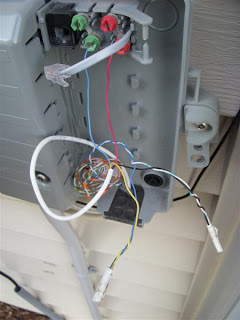
Looking at this picture you see that Black is twisted to White and Yellow is twisted to Green. The Black and Yellow are the colors from the Telephone company the Green and White is from the installation cable.
The first thing to do is remove the live connection from the NID posts. Unplug the RJ11 connection as the picture shows. I like to mark my wires with masking tape just for reference, because you never know what can come up while your working these. Untwist the ground pair (Yellow, Black) mark them and let hang.
You will now connect the Red and Green that was originally connected to the NID posts to the pair that the Yellow and Black were originally on. Basically just switching the wiring connections.
I recommend using Scotchlok's from 3M to connect your wires instead of twisting them together, but if your in a pinch ~ twist and cap the connections.
Here is a link to Digikey to purchase Scotchloks.
You now should have a Black and Yellow pair to connect. Wrap those on the NID posts the Red and Green were on and head back inside to your wall jack.
At the wall jack you need to remove the Red and Green pair and place the Black and Yellow pair on. So if Red and Green are on the 1 and 2 connects place the Black and Yellow pair on the 1 and 2 and the Red and Green on the 3 and 4.
You now have electricity going to that jack from the NID on the Black and Yellow pair. You can plug in your DSL connection. Turn on the Modem and get sync. This will allow you to get an Internet connection for your Vonage system and computer. You can test this by plugging in a phone to the jack and you should get a busy signal.
All the other phones in the house will be on the Red and Green pair and have no electricity going to them. So when you pick up another phone in the house you will hear no busy signal or dial tone just yourself breathing into the phone.
This is where you must make a decision. You can either run a telephone cable to a non charged outlet or you can wire up a dual jack wall plate.
Here is a crappy picture of the reverse side of a dual jack plate.
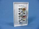 I prefer the dual jack method. This way you have a live DSL connection and a dead Vonage connection all in one spot.
To do it just connect the Red and Green pair to the 1 and 2 connects on the plate back. just as all the others in the house were/are. All wall plates are wire color coded to make things simpler.
I can only recommend that you test continuity with a tone tester or at least a voltmeter before you plug your phone in. Also make sure you close up your NID box outside to protect if from the weather once you are finished.
This may seem confusing while reading it, but once you get into it you will see very quickly what is going on. You are just taking voltage from one set of wires and putting it on another then ending that connection on the other end.
I've run into problems with older house wiring that this will just not work due to other IW issues. I cannot stress enough that color scheme and NID types vary all across the world and this blog post is by no means an end all solution to the DSL Vonage problems. If you continue to have problems you can also check on the Vonage forums.
JS
If you just have one phone that you want connected to Vonage then everything will work out fine. Its when you plug the Vonage Router via the Telephone cable into the phone jack/biscuit you get a busy signal from the phone.
This is because with voltage running through the pair your Vonage system will send a busy signal to the tele set.
To fix this you need to send the voltage through a separate pair on the jack and have the rest of the house set to the other set.
WARNING: NID's come in all shape and sizes. It would be best to research the particular NID you are working on before continuing. Most telephone companies use Red,Green,Black,Yellow wires for working pair. This is not a hard set rule and may be different in your area. I take no responsibility for any injury you may sustain or device's you may break in the process.
For simplicity sake I will use the Red and Green pair as the current pair in use with Black and Yellow as the second pair. The pictures I'll use are random ones I've gotten from the Internet.
On the NID outside the building you will see Red and Green attached to the NID Posts. This picture uses the Red and Blue wires for a live connection.

Looking at this picture you see that Black is twisted to White and Yellow is twisted to Green. The Black and Yellow are the colors from the Telephone company the Green and White is from the installation cable.
The first thing to do is remove the live connection from the NID posts. Unplug the RJ11 connection as the picture shows. I like to mark my wires with masking tape just for reference, because you never know what can come up while your working these. Untwist the ground pair (Yellow, Black) mark them and let hang.
You will now connect the Red and Green that was originally connected to the NID posts to the pair that the Yellow and Black were originally on. Basically just switching the wiring connections.
I recommend using Scotchlok's from 3M to connect your wires instead of twisting them together, but if your in a pinch ~ twist and cap the connections.

Here is a link to Digikey to purchase Scotchloks.
You now should have a Black and Yellow pair to connect. Wrap those on the NID posts the Red and Green were on and head back inside to your wall jack.
At the wall jack you need to remove the Red and Green pair and place the Black and Yellow pair on. So if Red and Green are on the 1 and 2 connects place the Black and Yellow pair on the 1 and 2 and the Red and Green on the 3 and 4.
You now have electricity going to that jack from the NID on the Black and Yellow pair. You can plug in your DSL connection. Turn on the Modem and get sync. This will allow you to get an Internet connection for your Vonage system and computer. You can test this by plugging in a phone to the jack and you should get a busy signal.
All the other phones in the house will be on the Red and Green pair and have no electricity going to them. So when you pick up another phone in the house you will hear no busy signal or dial tone just yourself breathing into the phone.
This is where you must make a decision. You can either run a telephone cable to a non charged outlet or you can wire up a dual jack wall plate.
Here is a crappy picture of the reverse side of a dual jack plate.
 I prefer the dual jack method. This way you have a live DSL connection and a dead Vonage connection all in one spot.
To do it just connect the Red and Green pair to the 1 and 2 connects on the plate back. just as all the others in the house were/are. All wall plates are wire color coded to make things simpler.
I can only recommend that you test continuity with a tone tester or at least a voltmeter before you plug your phone in. Also make sure you close up your NID box outside to protect if from the weather once you are finished.
This may seem confusing while reading it, but once you get into it you will see very quickly what is going on. You are just taking voltage from one set of wires and putting it on another then ending that connection on the other end.
I've run into problems with older house wiring that this will just not work due to other IW issues. I cannot stress enough that color scheme and NID types vary all across the world and this blog post is by no means an end all solution to the DSL Vonage problems. If you continue to have problems you can also check on the Vonage forums.
JS
Wednesday, December 17, 2008
Telnet in Vista
What happened to Telnet on the Vista OS?????
Telnet is a great application for basic remote administration of computers. Sadly in Vista though it is turned OFF by default. This only adds to the frustration that is the Vista Albatross.
To turn it on you have to get to Programs and Features in the Vista complex. To get here do this:
Start Pearl > Control Panel > Programs and Features > Turn Windows features on and off (Left Hand Side of Window on bottom) > Telnet Client
Enable it by placing a check mark beside it and click OK and/or Close X all the way out to the desktop. Now go to the Run command and type in telnet.
A telnet session will open allowing you to connect to a remote host device.
Frustrating at first, but easy to remedy in the end...
JS
Telnet is a great application for basic remote administration of computers. Sadly in Vista though it is turned OFF by default. This only adds to the frustration that is the Vista Albatross.
To turn it on you have to get to Programs and Features in the Vista complex. To get here do this:
Start Pearl > Control Panel > Programs and Features > Turn Windows features on and off (Left Hand Side of Window on bottom) > Telnet Client
Enable it by placing a check mark beside it and click OK and/or Close X all the way out to the desktop. Now go to the Run command and type in telnet.
A telnet session will open allowing you to connect to a remote host device.
Frustrating at first, but easy to remedy in the end...
JS
Wednesday, December 10, 2008
HyperTerminal Alternatives
When consoling into a router you have generally use some type of program to view the internals of the router. For Cisco routers I used to use Hyperterminal. It is a free program and is included on all Windows OS pre Vista.
You can find it under the Programs || Accessories || Communications || Hyperterminal
If you would like Hyperterminal on your Vista OS you can still get HyperTerminal from Hilgraeve, the company that created it, but you will have to purchase the Personal Edition. Link Here
One thing comes to mind when thinking about Hyperterminal. That is the burning, dizzying sensation I get from looking at black on white text for over two hours.
As great as Hyperterminal is or was there are alternatives out there for the Windows and Linux systems.
Tera Term:
This product was created in 1996 by T. Teranishl for the Windows 3.1/95/NT/ it supported Telnet, SSH and serial port connections. The new version picked up where the older one left off and is still free with a ton of extended options.
You can customize Tera Term to look how you would like. I prefer the Green text on Black background ala the Matrix code.
Real Term:
For Linux I prefer Real Term. It looks a lot like a tty connection, but has a GUI at the bottom of the screen that allows for serious configuration and testing. It can be used for far more serious stuff than just a simple COM connection. I have never used it though for anything more than a tool to get into a Cisco router.
These are just two products from many that are out there that I prefer. I am sure there are better tools out there so do a web check and see what you can find and let me know.
JS
You can find it under the Programs || Accessories || Communications || Hyperterminal
If you would like Hyperterminal on your Vista OS you can still get HyperTerminal from Hilgraeve, the company that created it, but you will have to purchase the Personal Edition. Link Here
One thing comes to mind when thinking about Hyperterminal. That is the burning, dizzying sensation I get from looking at black on white text for over two hours.
As great as Hyperterminal is or was there are alternatives out there for the Windows and Linux systems.
Tera Term:
This product was created in 1996 by T. Teranishl for the Windows 3.1/95/NT/ it supported Telnet, SSH and serial port connections. The new version picked up where the older one left off and is still free with a ton of extended options.
You can customize Tera Term to look how you would like. I prefer the Green text on Black background ala the Matrix code.
Real Term:
For Linux I prefer Real Term. It looks a lot like a tty connection, but has a GUI at the bottom of the screen that allows for serious configuration and testing. It can be used for far more serious stuff than just a simple COM connection. I have never used it though for anything more than a tool to get into a Cisco router.
These are just two products from many that are out there that I prefer. I am sure there are better tools out there so do a web check and see what you can find and let me know.
JS
Monday, December 8, 2008
Making your own Butt Set
My beautiful Butt Set broke on me while on site one day and I had to make one on the fly to get the job done this is what I did....
To make your own Butt Set, Linemans Headset, or Beige Box you will need:
A land line phone (not a cordless phone)
Two alligator clips
Soldering Iron and Solder
Scissors or wire cutters
Remove the cord from both ends of the phone.
I prefer to use the straight cord with the RJ11's and not the curly cord with RJ11's. It just gets all tangled and creates an unruly mess.
Cut one end of the cord and peel back the vinyl/plastic coating exposing the wires bare with the scissors or wire cutters.
Split open the wire end/open end of the alligator clips so you will have room to drop solder onto the wires and have a clear view of what you are doing. Scrap the open end of the clip with your Scissors to remove any coatings that are put on the clip at the manufacture leaving bare metal to bare metal connection between the wire and clip.
Place the Green wire onto the end of the alligator clip and drop a little bit of solder on it making a clean connection. Let it cool.... Be careful the clip connection is delicate and can break easily.
Now do the same with the Red wire.
Color code is not really an issue just use two wires from the cord and solder them onto the alligator clips. I try to keep them color coordinated for detail and simplicity. These will be connected to the posts later for call outs.
Now that the clips have been added to the wires plug the other end into the phone set. Make sure the phone is on Tone not Pulse.
You now have a working Butt Set and to test it you can either go to a 66/100 block, open up your phone Biscuit or go to a NID splitter and connect the one clip to one post and the other clip to the other post and make calls.
I didn't go into great detail or add pictures to this because Butt Sets can be used illegally. If you have any type of Telco experience you will understand this tutorial without any further explanation.
To make your own Butt Set, Linemans Headset, or Beige Box you will need:
A land line phone (not a cordless phone)
Two alligator clips
Soldering Iron and Solder
Scissors or wire cutters
Remove the cord from both ends of the phone.
I prefer to use the straight cord with the RJ11's and not the curly cord with RJ11's. It just gets all tangled and creates an unruly mess.
Cut one end of the cord and peel back the vinyl/plastic coating exposing the wires bare with the scissors or wire cutters.
Split open the wire end/open end of the alligator clips so you will have room to drop solder onto the wires and have a clear view of what you are doing. Scrap the open end of the clip with your Scissors to remove any coatings that are put on the clip at the manufacture leaving bare metal to bare metal connection between the wire and clip.
Place the Green wire onto the end of the alligator clip and drop a little bit of solder on it making a clean connection. Let it cool.... Be careful the clip connection is delicate and can break easily.
Now do the same with the Red wire.
Color code is not really an issue just use two wires from the cord and solder them onto the alligator clips. I try to keep them color coordinated for detail and simplicity. These will be connected to the posts later for call outs.
Now that the clips have been added to the wires plug the other end into the phone set. Make sure the phone is on Tone not Pulse.
You now have a working Butt Set and to test it you can either go to a 66/100 block, open up your phone Biscuit or go to a NID splitter and connect the one clip to one post and the other clip to the other post and make calls.
I didn't go into great detail or add pictures to this because Butt Sets can be used illegally. If you have any type of Telco experience you will understand this tutorial without any further explanation.
Thursday, December 4, 2008
Vonage and Multiple Phones
Vonage is a great service. It works with just about every existing phone set up there is. Well.... almost.
I've been on some calls and seen some pretty crazy stuff that was unfixable. Usually it's the inside wiring that needs to be replaced or some rouge phone that won't work, because it was installed oddly.
Some of the easier calls I get are when a customer has multiple phones and only one is ringing through Vonage.
This is a very easy fix.
First you have to make sure that at least one phone is working with Vonage. That will make sure the electricity is off the NID and disconnected from the telephone pole and the number was ported on Vonage's end. If you don't hear any static or a busy tone or any other strange issues then you can assume all is well.
You will need:
Phone Line Splitter
2 Telephone Cords
Use a telephone line splitter and plug it into a wall jack where your old phone used to be when you had a Telco carrier.
Plug one phone cord into one side of the splitter and run that to the telephone that was plugged into your Vonage router/ATA.
Plug another phone cord into the other side and run that to the Vonage router/ATA where the working phone was plugged in at.

After it set up you can do a test call to 1-800-444-4444 and you will get a read back from MCI about what number you are calling from.
This seems like a no brainer and to regular telco guys in the field this is day one stuff, but I can't count how many calls I get that are all fixed with this set up. I just keep in mind that this is the stuff I get paid to know not the customer and I always explain to them what I did and how it works when I am finished.
If you want more in depth discussion about Vonage's Services and fixes for complex or baffling problems with the Vonage Service go to the Vonage Forum. Here you will find other field techs and intelligent people with WAY more experience than me that can answer just about every question you will have.
JS
I've been on some calls and seen some pretty crazy stuff that was unfixable. Usually it's the inside wiring that needs to be replaced or some rouge phone that won't work, because it was installed oddly.
Some of the easier calls I get are when a customer has multiple phones and only one is ringing through Vonage.
This is a very easy fix.
First you have to make sure that at least one phone is working with Vonage. That will make sure the electricity is off the NID and disconnected from the telephone pole and the number was ported on Vonage's end. If you don't hear any static or a busy tone or any other strange issues then you can assume all is well.
You will need:
Phone Line Splitter
2 Telephone Cords
Use a telephone line splitter and plug it into a wall jack where your old phone used to be when you had a Telco carrier.
Plug one phone cord into one side of the splitter and run that to the telephone that was plugged into your Vonage router/ATA.
Plug another phone cord into the other side and run that to the Vonage router/ATA where the working phone was plugged in at.
Working Diagram:

After it set up you can do a test call to 1-800-444-4444 and you will get a read back from MCI about what number you are calling from.
This seems like a no brainer and to regular telco guys in the field this is day one stuff, but I can't count how many calls I get that are all fixed with this set up. I just keep in mind that this is the stuff I get paid to know not the customer and I always explain to them what I did and how it works when I am finished.
If you want more in depth discussion about Vonage's Services and fixes for complex or baffling problems with the Vonage Service go to the Vonage Forum. Here you will find other field techs and intelligent people with WAY more experience than me that can answer just about every question you will have.
JS
Wednesday, December 3, 2008
Wireless Setup Extended...
I want to expand upon the previous post of the wireless setup.
When I stated that you should use the same SSID that was for the simplicity of network identification. If you have a Public and Private network make one named Private so you know when setting up the AP's that it needs to have access to all things company shared. Mark the other network Public to keep it Internet accessible only. It's all about ease of installation and documentation.
Speaking on ease of installation another thing that helps is keeping all of your devices within the same block or row on your switch. It will be easier a year down the road when you are looking at documentation when problems occur and it will be easier for everyone when you are finishing the installation and go to jack all the ports.
I've done installs where the switch had every other port configured to VOIP then every other port configured to computers and 4 ports in the left and right block dedicated to the printers with two ports configured for trunking. What a mess this makes. It is so confusing to the installers running data lines and to any future network admins reading your documentation. Before you know it you have a spaghetti mess of cables, everyone is confused and the install doesn't look professional.
Some would say a set up like that is for security purposes so if someone gets in they will not know where they are at. I agree to an extent, but really, if some hacker gets into your router/switch you failed. It wouldn't matter anyways - if they have gotten this far then they will know the difference in set up on port configurations to get to the proper devices.
Anyways enough of that stuff. Here are my recommendations for wireless AP setup:
Step 1: Test your switch by connecting into it with a cable and see if DNS, DHCP, etc... is set up correctly and you can get out to the Internet.
Step 2: Plug in your WAP and test it with any of the tools mentioned before or even your Windows Network Finder application. Verify it is running and the SSID is what you set it to.
Step 3: Do some testing with the encryption turned off. Make sure you can access file shares or what ever it is that you want the client to do when this is fully functional. This will keep things simple and easier to trouble shoot if a problem arises.
Step 4: Add PSK, WEP, or WPA authentication and connect with a simple Pre Shared Key. Check all file shares and verify Internet connectivity.
Now that you see everything works finish up and set up your AP for proper security authentication to lock it down. Finalize the network for whatever your organization will need for security and take the AP to the desired location in the building and add it to the network permanently.
Ideally you would want to do this in a lab setting, but in most cases (at least for me) it is done on the fly in a production environment after hours.
JS
When I stated that you should use the same SSID that was for the simplicity of network identification. If you have a Public and Private network make one named Private so you know when setting up the AP's that it needs to have access to all things company shared. Mark the other network Public to keep it Internet accessible only. It's all about ease of installation and documentation.
Speaking on ease of installation another thing that helps is keeping all of your devices within the same block or row on your switch. It will be easier a year down the road when you are looking at documentation when problems occur and it will be easier for everyone when you are finishing the installation and go to jack all the ports.
I've done installs where the switch had every other port configured to VOIP then every other port configured to computers and 4 ports in the left and right block dedicated to the printers with two ports configured for trunking. What a mess this makes. It is so confusing to the installers running data lines and to any future network admins reading your documentation. Before you know it you have a spaghetti mess of cables, everyone is confused and the install doesn't look professional.
Some would say a set up like that is for security purposes so if someone gets in they will not know where they are at. I agree to an extent, but really, if some hacker gets into your router/switch you failed. It wouldn't matter anyways - if they have gotten this far then they will know the difference in set up on port configurations to get to the proper devices.
Anyways enough of that stuff. Here are my recommendations for wireless AP setup:
Step 1: Test your switch by connecting into it with a cable and see if DNS, DHCP, etc... is set up correctly and you can get out to the Internet.
Step 2: Plug in your WAP and test it with any of the tools mentioned before or even your Windows Network Finder application. Verify it is running and the SSID is what you set it to.
Step 3: Do some testing with the encryption turned off. Make sure you can access file shares or what ever it is that you want the client to do when this is fully functional. This will keep things simple and easier to trouble shoot if a problem arises.
Step 4: Add PSK, WEP, or WPA authentication and connect with a simple Pre Shared Key. Check all file shares and verify Internet connectivity.
Now that you see everything works finish up and set up your AP for proper security authentication to lock it down. Finalize the network for whatever your organization will need for security and take the AP to the desired location in the building and add it to the network permanently.
Ideally you would want to do this in a lab setting, but in most cases (at least for me) it is done on the fly in a production environment after hours.
JS
Tuesday, December 2, 2008
Outlook and the wrong MAPI
After installing a trial offer of Microsoft Office 2007 you have the option of purchasing a copy, use the current copy in limited form, or uninstall it.
If you try to reinstall Office 2000 or Office 2003 over the copy of Office 07 then start Outlook you will get a warning pop up stating that you are using the wrong version of the MAPI32.dll file.
First thing to do is remove MS Office 07 from the Add/Remove Programs applet. After this you have two options of getting this fixed.
Option 1:
Go to C:\winnt\system32 or C:\windows\system32, double-click Fixmapi.exe program.
If you can't find the program and don't want to take the time to search for it try -
Option 2:
Find the MSMAPI folder. It should be located at C:\Program Files\Common Files\System\MSMAPI and should contain a folder called 1033.
Rename the MSMAPI folder to MSMAPI.old.
Close all the windows and start Outlook again.
I used C:\ as the primary drive for this example. If you cannot find the folders where the example stated then do a search for them and you should be able to find them.
JS
If you try to reinstall Office 2000 or Office 2003 over the copy of Office 07 then start Outlook you will get a warning pop up stating that you are using the wrong version of the MAPI32.dll file.
First thing to do is remove MS Office 07 from the Add/Remove Programs applet. After this you have two options of getting this fixed.
Option 1:
Go to C:\winnt\system32 or C:\windows\system32, double-click Fixmapi.exe program.
If you can't find the program and don't want to take the time to search for it try -
Option 2:
Find the MSMAPI folder. It should be located at C:\Program Files\Common Files\System\MSMAPI and should contain a folder called 1033.
Rename the MSMAPI folder to MSMAPI.old.
Close all the windows and start Outlook again.
I used C:\ as the primary drive for this example. If you cannot find the folders where the example stated then do a search for them and you should be able to find them.
JS
Subscribe to:
Posts (Atom)

 Posts
Posts

